
Ultimate Guide to Blueprint Takeoffs

Blueprint takeoffs are the backbone of construction estimates. They involve analyzing blueprints to calculate materials, labor, and equipment needed for a project. Mistakes in takeoffs can lead to financial losses or uncompetitive bids. Today, AI tools like ScopeTakeoff can complete takeoffs in 20–30 minutes versus 6–8 hours manually, but understanding the process is still important. Here’s what you need to know:
- What It Is: Blueprint takeoffs identify and measure materials, labor, and equipment based on project blueprints.
- Why It Matters: Errors can result in lost contracts, delays, or unexpected costs.
- Blueprint Types: Focus on architectural, structural, MEP (Mechanical, Electrical, Plumbing), and schedules for accurate takeoffs.
- Steps: Review plans, select relevant pages, count items, measure dimensions, and verify material lists.
- Manual vs Digital: Digital tools are faster, more accurate, and better for handling revisions.
Accurate takeoffs ensure precise bids, reduce waste, and save time. Digital tools like ScopeTakeoff simplify the process with features like automated calculations and trade-specific estimating software, helping subcontractors stay competitive.
What Are Blueprint Takeoffs?
Definition and Purpose
A blueprint takeoff, often referred to as a material or quantity takeoff, is the process of analyzing construction drawings to identify and measure all the materials required for a project. Think of it as the groundwork for creating an estimate. While the takeoff provides raw numbers – like how many studs or the square footage of drywall – the estimate assigns costs, labor rates, overhead, and profit to these quantities.
For subcontractors, this step comes right after receiving the project plans. The data from the takeoff helps determine whether the project aligns with their capacity and provides the foundation for crafting bids that balance competitiveness with profitability. Beckie Dashiell from Joist explains it well:
A takeoff for construction is part of the estimating process. It’s where you figure out exactly what materials you’ll need to finish the job and how much of each.
A detailed takeoff accounts for material quantities (like counts, linear feet, surface area, or volume), estimated labor hours for installation, necessary equipment (such as cranes or lifts), and waste factors. Subcontractors focus only on materials relevant to their trade – for instance, a drywall subcontractor will zero in on wallboard, corner beads, and joint compound using drywall estimating software, leaving out items like electrical conduit.
Mastering this process is critical for subcontractors because it directly impacts the accuracy of bids and the profitability of projects. A precise takeoff can mean the difference between winning a job and losing money or missing out on an opportunity altogether.
Why Accurate Takeoffs Matter for Subcontractors
Mistakes in takeoffs can lead to costly consequences. Underestimating materials may result in financial losses and delays, while overestimating can make your bid less competitive and cost you the contract. For example, on a 500-sheet drywall job, a mere 10% error in waste calculation could result in a $700 discrepancy in material costs.
Dustin Elliott, Director of Product Operations at Buildxact, puts it bluntly:
Without accurate quantities, the costs that follow are guesswork.
Accurate takeoffs help avoid over-ordering, which cuts into profits, or under-ordering, which can delay projects and lead to extra shipping costs. They also allow subcontractors to translate material quantities into labor hours using production rates. This helps determine crew size and project timelines. In competitive bidding, precision is key – underbid, and you risk losing money; overbid, and you might lose the job.
sbb-itb-4ee4ad4
Construction Quantity Take-Offs – COMPLETE Guide
Blueprint Components You Need to Know
Getting accurate takeoffs starts with understanding all the parts of a blueprint. Construction blueprints aren’t just one document – they’re a collection of drawings, each with a specific purpose. For subcontractors, knowing which sheets to focus on and what details to extract is essential. Missing key information from even one drawing could throw off your material estimates completely.
Blueprints generally fall into four main categories: architectural, structural, MEP (Mechanical, Electrical, Plumbing), and schedules. Each type uses its own symbols, scales, and conventions. According to PlanUpPro, 52% of construction rework happens because of communication and project data errors, including misreading plans. That’s why understanding what each drawing includes – and what it doesn’t – is critical for getting your takeoffs right.
Architectural Drawings
Architectural drawings, marked with an "A" prefix, focus on the layout and finishes of the project. These sheets include floor plans, elevations, sections, and finish details. Subcontractors often spend the most time here during takeoffs.
- Floor plans give an overhead view, showing wall placements, room sizes, door swings, window locations, and flooring materials.
- Elevations show the vertical faces of the building, helping calculate materials like siding, bricks, and exterior finishes.
- Sections provide cross-sectional views to reveal hidden elements like insulation, wall assemblies, and roof pitches.
Emils Berzins of PlanUpPro highlights the importance of sections:
Sections are where you catch clashes that floor plans can’t show. A duct that fits on the mechanical plan might not fit when you see it in section, competing with a beam and a pipe in the same 14-inch ceiling cavity.
Architectural drawings also include detailed views of complex elements like staircases, wall joints, or millwork. These require precise material calculations. Be mindful of the scale on each sheet – it can vary from 1/4" = 1′-0" for floor plans to 3" = 1′-0" for detailed drawings. Cross-referencing schedules is also important for confirming counts of doors, windows, and other components.
Once you’ve understood the architectural layout, the next step is diving into the structural framework, which outlines the building’s support systems.
Structural Drawings
Structural drawings, labeled with an "S" prefix, detail the building’s framework – foundations, beams, columns, load paths, and reinforcing steel. While architectural plans show where walls are located, structural plans explain how those walls are supported, whether by footings, beams, or other elements.
For subcontractors in concrete, masonry, or framing, these drawings are essential for calculating materials like rebar, steel beams, or lumber. Even if you’re not directly working on these elements, understanding the structural layout helps coordinate your tasks. For example, a drywall contractor needs to know where steel columns are to plan for furring and finishing.
Cross-referencing architectural and structural plans is crucial. An architectural plan might show 12,000 sq. ft. of drywall, but a structural plan could reveal that 4,500 sq. ft. of that area is actually reinforced concrete slab. Reviewing architectural, structural, and MEP plans together ensures there are no conflicts in dimensions or placements.
MEP Drawings
MEP drawings focus on trade-specific systems and installations. These are broken down into three disciplines:
- Mechanical (M-sheets): HVAC layouts, ductwork routes, air diffusers, and return grilles.
- Electrical (E-sheets): Power and lighting plans, panel schedules, outlets, switches, fixtures, and conduit runs.
- Plumbing (P-sheets): Water supply, waste and vent systems, gas piping, and riser diagrams showing vertical pipe runs between floors.
For accurate takeoffs, count devices like outlets or fixtures and measure the linear footage of pipes, conduit, or ductwork by diameter and material type. Don’t forget vertical measurements in riser diagrams, as these are often overlooked. Overlaying MEP plans with architectural and structural drawings is key to spotting potential clashes, like a duct running into a beam in a tight ceiling cavity.
Schedules and Notes
Schedules are tables included in the drawing set that list counts and specifications for items like doors, windows, hardware, light fixtures, and finishes. These are often embedded in architectural or MEP sheets and are the go-to source for confirming quantities.
General notes outline quality standards and installation guidelines. Always update your takeoffs based on revision clouds marking changes. Pay close attention to "VIF" (Verify In Field) notes, which indicate that certain dimensions need to be measured on-site before ordering materials. Common abbreviations like AFF (Above Finish Floor), OC (On Center), GYP BD (Gypsum Board), and NIC (Not In Contract) are also frequently used.
As Emils Berzins from PlanUpPro explains:
The legend is the law.
Knowing how to read symbols, legends, and notes ensures you don’t miss critical details that could derail your estimate.
How to Perform Blueprint Takeoffs: Step-by-Step
Performing a blueprint takeoff involves a detailed process to ensure every material and dimension is accounted for accurately. The success of a bid often hinges on how carefully this process is executed. Dustin Elliott from Buildxact emphasizes this point:
A takeoff determines whether an estimate reflects the real scope of the build. When quantities are incomplete or measured manually across plans and spreadsheets, mistakes surface later in material shortages, unexpected costs, or bids that no longer hold once the project begins.
Here’s a breakdown of how to approach this process to avoid costly errors.
Step 1: Review Plans and Specifications
Start by thoroughly reviewing all drawing types and specifications. Pay attention to revision clouds, title block details (like project phase, sheet description, and revision date), and general notes for terms such as "NIC" (Not In Contract) and "TYP" (Typical). Cross-check architectural, structural, and MEP (Mechanical, Electrical, Plumbing) drawings to identify which phases pertain to your trade and to spot any inconsistencies between drawing types.
Step 2: Select the Right Drawing Pages
Once you’ve reviewed the plans, focus on the specific pages relevant to your trade. For instance:
- Use floor plans for drywall or flooring.
- Refer to MEP sheets for electrical or plumbing work.
- Check structural drawings for concrete or framing needs.
If you’re using digital takeoff software, use keyword searches to quickly locate the relevant pages. Always verify the scale on each page, calibrating your tools to known dimensions. Watch for sheets marked "N.T.S." (Not to Scale) and cross-reference different drawing types to uncover potential conflicts or missing details.
Step 3: Count Individual Items
Counting items accurately is essential for a precise estimate. This includes items like doors, windows, light fixtures, outlets, and plumbing fixtures. Use a systematic approach to avoid missing or duplicating items. Tools like color coding or digital markup can help you track progress as you go.
Compare your counts with schedules included in the drawings. These schedules provide a detailed list of units by type and location. Be aware that dimensions in schedules often refer to "Rough Openings" (framed openings) rather than finished sizes. Document any assumptions or discrepancies, and if counts differ between drawings, submit an RFI (Request for Information) to the architect. Digital tools can also automate the counting process where applicable.
Step 4: Measure Linear, Area, and Volume Quantities
Measure linear, area, and volume quantities based on the type of material you’re working with. Here’s a quick guide:
- Linear measurements (in linear feet) apply to items like pipes, rebar, baseboards, and framing plates.
- Area measurements (in square feet) are used for materials such as drywall, flooring, roofing, and insulation.
- Volume measurements (in cubic yards or cubic feet) are needed for materials like concrete, asphalt, and earthwork.
Use floor plans for horizontal dimensions and elevations or sections for vertical measurements (e.g., wall heights, ceiling depths). If a measurement isn’t explicitly noted, you can use deductive techniques – subtracting known segments from total dimensions. Be sure to distinguish between "Face of Stud" (framing face) and finished wall dimensions for accurate material estimates. Finally, convert your measurements into purchasing units, such as converting cubic feet of concrete into cubic yards or determining the number of 80-lb bags required.
| Measurement Type | Common Units | Typical Materials |
|---|---|---|
| Linear | Linear Feet (LF) | Pipes, conduits, baseboards, trim, rebar |
| Area | Square Feet (SF) | Drywall, flooring, roofing, insulation |
| Volume | Cubic Yards (CY) | Concrete slabs, earthwork, asphalt |
Step 5: Compile and Verify Your Material Lists
Organize all your data into a takeoff sheet or spreadsheet. Include details like the item description, unit of measurement, raw quantity, waste factor, and adjusted total. Waste factors typically range from 5% to 10% and account for cutting, mistakes, or breakage.
Double-check elevations and sections to identify any "hidden" materials, such as wall insulation or structural supports, that may not appear on floor plans. Clearly document inclusions and exclusions to define the scope of your bid.
If you’re using digital takeoff software like ScopeTakeoff (https://scopetakeoff.com), leverage features like real-time collaboration and automated trade calculations. These tools help ensure everyone is working from the same data set, reducing the risk of errors. The final verification step is critical to catching discrepancies before they lead to costly issues on the job site.
Manual vs Digital Takeoff Methods
Manual vs Digital Blueprint Takeoff Methods Comparison
The way you choose to handle takeoffs – manually or digitally – can significantly affect both the time it takes to prepare a bid and the accuracy of your estimates. While manual methods have long been a go-to for contractors, digital tools are reshaping how subcontractors analyze blueprints.
Comparison: Manual vs Digital Takeoffs
Manual takeoffs involve working with printed plans, scale rulers, and spreadsheets. You measure dimensions by hand, mark up plans manually, and record quantities in Excel or on paper. While this method is simple, it’s time-consuming and prone to mistakes. Small rounding errors from hand measurements can add up, especially on complex projects.
Digital takeoff software, on the other hand, eliminates many of these issues. Once the scale is calibrated, the software ensures precise measurements. As PlanSnapper explains:
Digital tracing eliminates the compounding ruler measurement errors of a paper takeoff once scale is set correctly.
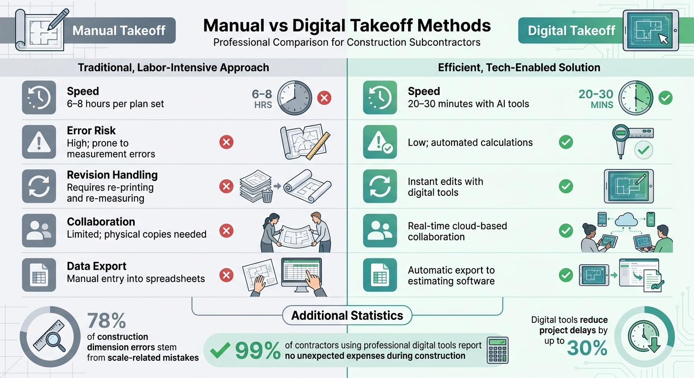
The difference in speed is striking. Tasks that might take 6 to 8 hours with manual methods can be completed in just 20 to 30 minutes using AI-powered tools.
| Feature | Manual Takeoff | Digital Takeoff |
|---|---|---|
| Speed | 6–8 hours per plan set | 20–30 minutes with AI tools |
| Error Risk | High; prone to measurement errors | Low; automated calculations |
| Revision Handling | Requires re-printing and re-measuring | Instant edits with digital tools |
| Collaboration | Limited; physical copies needed | Real-time cloud-based collaboration |
| Data Export | Manual entry into spreadsheets | Automatic export to estimating software |
Digital methods particularly excel when plans change. Adjusting a digital trace takes seconds, while manual methods often mean starting from scratch. Additionally, cloud-based tools allow teams to collaborate in real-time, something that’s nearly impossible with printed plans.
Benefits of Using Digital Takeoff Software
Beyond the basic advantages of speed and accuracy, digital takeoff software offers features that streamline every aspect of the process.
With digital tools, repetitive tasks like tallying measurements are automated, but you still control the critical decisions. Once you calibrate the scale (e.g., using a known dimension like a door width), the software automatically converts all measurements to real-world dimensions. This eliminates the risk of ruler errors and manual calculations.
One standout feature is assembly-based estimating. Instead of counting each component individually, you can use pre-built assemblies where a single measurement calculates all related materials. For instance, measuring the linear feet of a wall in ScopeTakeoff (https://scopetakeoff.com) can automatically account for studs, plates, drywall, and fasteners, based on trade-specific libraries. This approach helps ensure no essential components are overlooked.
Digital tools also improve organization. Color coding lets you systematically mark completed sections, whether you’re counting 50 outlets or 400. This prevents double-counting or missed areas. Plus, the permanent digital record simplifies audits and bid reviews.
Contractors report significant benefits from digital takeoffs, including project delay reductions of up to 30% and fewer cost surprises – 99% of contractors using professional digital tools report no unexpected expenses during construction. These tools are especially valuable for managing multi-discipline projects that would be nearly impossible to track on paper.
For subcontractors handling multiple trades, platforms like ScopeTakeoff offer features tailored to specific needs, such as automatic trade calculations, proposal generation, and team collaboration. By automating the tedious measurement work, these tools let you focus on interpreting the project scope, understanding site conditions, and making expert judgment calls.
Common Takeoff Mistakes and How to Avoid Them
Even seasoned subcontractors can sometimes make slip-ups during takeoffs, which can throw off bid accuracy. Knowing where these mistakes tend to happen can help you catch issues early and avoid costly problems. Below are some frequent pitfalls and practical ways to steer clear of them.
Misreading Scales and Dimensions
Did you know that 78% of construction dimension errors stem from scale-related mistakes? Most of these occur because measurements are scaled incorrectly rather than due to misreading dimension lines. A common culprit is using the wrong side of an architect’s scale ruler, which typically has 11 different faces.
Digital files add another layer of complexity. If files are exported incorrectly, the scale can shift. Similarly, printing ARCH D plans (24" x 36") on ANSI D paper (22" x 34") shrinks the drawing by about 6%, which carries over to manual measurements.
Here’s how to avoid these issues: always verify the graphic scale bar printed on each sheet. Use a ruler to check it or calibrate your digital tools to match. For PDFs, you can click two endpoints of a known dimension – like a 3-foot door – and input the actual measurement to ensure accuracy. When you see notes like "Do Not Scale" or "N.T.S." (Not to Scale), rely on labeled dimensions instead.
Missing Revisions and Updates
Using outdated plans is one of the quickest ways to create rework headaches. Always check the title block for revision history before starting your takeoff. Architects often highlight changes with revision clouds, and the cover sheet usually lists the latest version of every drawing.
Staying current with updates isn’t just about scaling – it’s about accuracy across the board. Spend 15–30 minutes reviewing all plans and revision notes before diving into your takeoff. Also, cross-check different drawing types, as changes in structural or MEP drawings can affect your architectural takeoff. Many digital takeoff tools let you overlay updated drawings on top of originals, making it easier to spot changes visually.
Forgetting Waste and Contingency Factors
When estimating materials, it’s easy to overlook waste and contingency factors. These two play different roles: waste accounts for physical material loss (like cutting or breakage), while contingency covers unexpected risks such as weather delays or equipment failures.
For waste, a general rule is to add 5–10%, but complex layouts with angles or soffits might require up to 20%. Keep track of actual waste rates from past projects to refine your future estimates. Use specific percentages based on the material – curved concrete forms, for instance, often need higher allowances than flat slabs. Assembly-based takeoffs can also help by automatically including related accessories like screws, tape, or joint compound, ensuring nothing critical is missed.
Poor Coordination Between Trades
Coordination issues between trades often arise during installation. For example, a duct shown on MEP drawings might conflict with a beam in the structural plans. Regularly cross-referencing all drawing types is essential.
Pay close attention to project specifications, especially Division 09 for finishes, as technical requirements or product changes might not appear on the blueprints. Document any unclear assumptions in your estimate report to avoid disputes later. Cross-reference floor plans, elevations, and sections to catch hidden materials or supports that might otherwise go unnoticed.
Conclusion
Mastering blueprint takeoffs is essential for securing profitable bids. As highlighted earlier, a solid takeoff forms the backbone of the entire estimating process. Tectonic Bid puts it perfectly:
A takeoff is the foundation of every construction estimate. Get it wrong, and everything downstream – your pricing, your proposal, your profit – is wrong too.
Accurate interpretation of architectural, structural, and MEP drawings is critical to avoid costly mistakes like underbidding or overbidding.
The transition from manual to digital takeoff methods has completely transformed the way subcontractors operate. What once took 6–8 hours can now be completed in just 20–30 minutes using digital tools, significantly increasing efficiency and allowing for more projects to be tackled . This shift also highlights the advanced features of tools like ScopeTakeoff.
ScopeTakeoff (https://scopetakeoff.com) offers subcontractors a streamlined approach to estimating with features like trade-specific assembly libraries for over 10 trades, automatic trade calculations, and proposal outputs – all for just $100 per person per month, with no annual contract required.
To ensure accurate and effective takeoffs, keep these practices in mind:
- Calibrate your scale using a known dimension to maintain precision.
- Check for plan revisions before starting to avoid outdated information.
- Apply appropriate waste factors to account for material loss.
- Cross-reference all drawing types to identify conflicts early.
The quality of your estimates depends on how well you understand the drawings. Take the time to thoroughly review notes, specifications, and details. A careful plan review can save thousands by preventing shortages and unexpected change orders. A disciplined approach to blueprint analysis is the foundation for crafting cost-effective, profitable bids.
FAQs
What’s the difference between a takeoff and an estimate?
A takeoff determines and quantifies the materials, labor, and equipment required for a project by analyzing blueprints or digital plans. Its primary focus is identifying the necessary resources. An estimate, on the other hand, takes the information from the takeoff and applies unit costs to calculate the total project cost. This includes factors like labor, materials, and overhead. In short, the takeoff supplies the raw data needed to prepare an accurate estimate.
How do I verify a plan’s scale before measuring?
Start by checking if the plan includes a predefined scale, such as 1/4"=1′ or 1:50. If it does, input this directly into your takeoff software.
If no scale is provided – or if the document has been resized – you’ll need to manually calibrate. To do this, measure a known dimension on the plan, like the width of a door or window, and adjust the scale settings in your software accordingly.
Getting the scale right is crucial for ensuring your measurements are accurate and your takeoffs are reliable.
What waste factor should I add for my trade?
When calculating material needs, the waste factor you include will depend on your specific trade and the materials you’re working with. For example, medium joints often require a waste factor of 15-20%, while tight joints may need 20-30% to account for potential loss. Adding an appropriate waste factor to blueprint takeoffs ensures your material estimates are accurate, helping you avoid running out of supplies or dealing with unnecessary leftovers. For most trades, a general range of 15-30% is standard practice.